
Embedded Programming
Individual Assignment:
- Write a program for a microcontroller development board.
- Demonstrate interaction with local input and/or output devices.
- Implement communication with remote wired or wireless devices.
- Extra Credit: use different languages &/or development environments
- Extra Credit: connect external components to the board
Programming
Embedded programming is the practice of developing software for embedded systems, which are specialized computing systems designed for specific functions within larger systems. Unlike general-purpose computers, embedded systems are usually dedicated to particular tasks and integrated into larger devices or products. Embedded programming entails writing code to govern the behavior of these systems. The code is typically written in languages like C, C++, or assembly language, depending on the system's requirements and the hardware it utilizes.
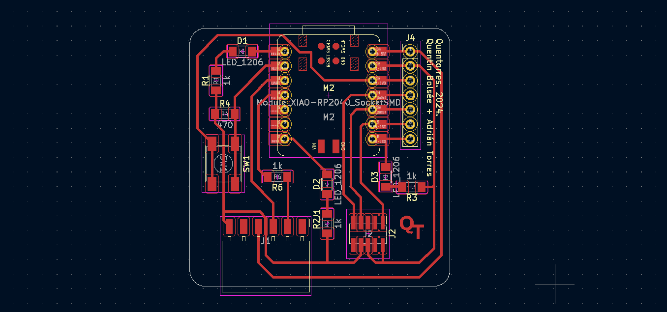
Quentorres Board,
The Quentorres Board, originally envisioned by Quentin Bolsée, underwent a substantial redesign led by Adrián Torres in 2024 during the Instructors Bootcamp in León. This updated version of the board offers enhanced versatility, specifically designed for programming both AVR Series 1 and 2 as well as ARM microcontrollers. It features essential input-output capabilities like buttons and LEDs, along with breakout pins for easy integration with external components.
Initially, I began programming the Quentorus board, which was built during electronics week. The first program I uploaded was to turn on the LED with the help of the push button on the Quentorus board. When the button is pressed, the LEDs will turn on and remain on until I stop pushing the button.
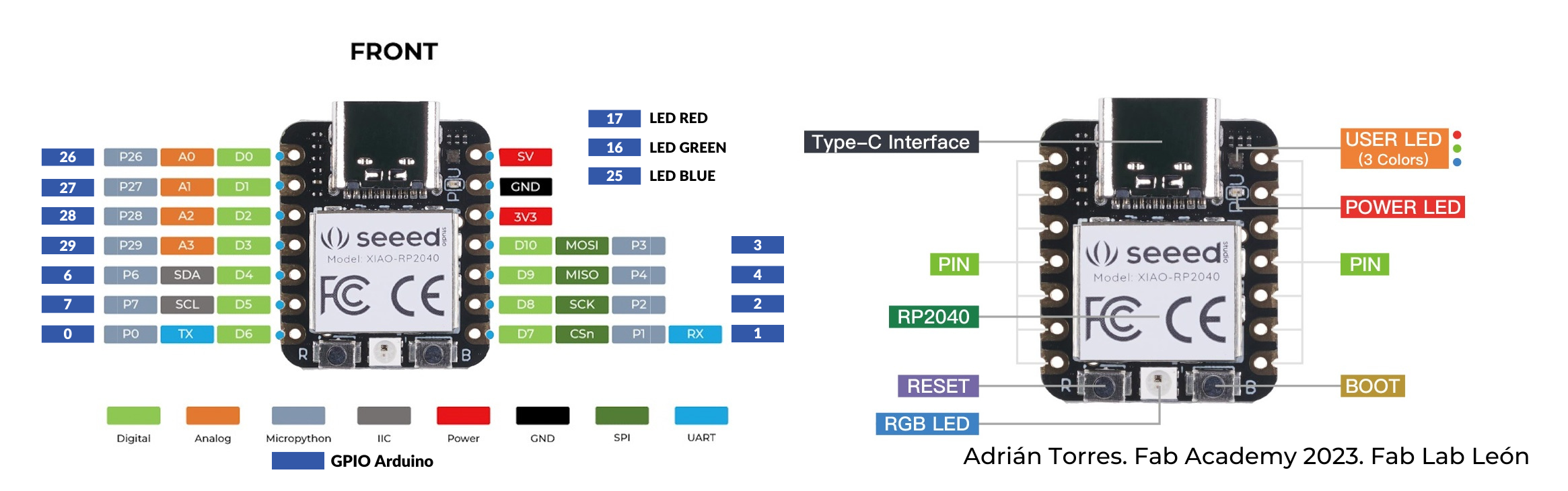
Seeed Studio XIAO RP2040
Seeed Studio XIAO RP2040 is compatible with the Raspberry Pi RP2040 ecosystem as they share the same RP2040 chip. It supports multiple languages including C / MicroPython / CircuitPython.
-
High Performance:
- Powered by Raspberry Pi 2040 chip
- Dual-core operating up to 133 MHz
- Equipped with 264KB of SRAM and 2MB of onboard flash memory
-
Ultra-small Design:
- Dimensions: 21 x 17.5mm
- Seeed Studio XIAO series classic form-factor
- Suitable for wearable devices
-
Multiple Development Interfaces:
- 2x buttons
- 11x digital / 4x analog pins
- 1x I2C interface
- 1x UART port
- 1x SPI port
- 1x SWD Bonding pad interface
-
Multiple Development Platforms:
- Support for Arduino, Micropython, and CircuitPython development
- Beginner-friendly and suitable for electronics enthusiasts
-
Perfect for Production:
- Breadboard-friendly & SMD design
- No components on the back
LED BLINK
step 1: set pins for LEDs and push button
step 2: get the input from the push button
step 3: analyze the value
step 4: if the value is high led ON, go to step 6
step 5: LEDs Off
step 6: go to step 3
Here is the code i used
const int buttonPin = 27;  // the number of the pushbutton pin
const int ledPin_1 = 26;    // the number of the LED pin
const int ledPin_2 = 0;
const int ledPin_3 = 1;
// variables will change:
int buttonState = 0;  // variable for reading the pushbutton status

void setup() {
  // initialize the LED pin as an output:
  pinMode(ledPin_1, OUTPUT);
  pinMode(ledPin_2, OUTPUT);
  pinMode(ledPin_3, OUTPUT);
  // initialize the pushbutton pin as an input:
  pinMode(buttonPin, INPUT);
}

void loop() {
  // read the state of the pushbutton value:
  buttonState = digitalRead(buttonPin);

  // check if the pushbutton is pressed. If it is, the buttonState is HIGH:
  if (buttonState == HIGH) {
    // turn LED on:
    digitalWrite(ledPin_1, HIGH);
    digitalWrite(ledPin_2, HIGH);
    digitalWrite(ledPin_3, HIGH);
  } else {
    // turn LED off:
    digitalWrite(ledPin_1, LOW);
    digitalWrite(ledPin_2, LOW);
    digitalWrite(ledPin_3, LOW);
  }
}
For the next task, I implemented the control of the LED with the push button. When the button is pressed once, if the LEDs are on, they will turn off. Conversely, if the button is pressed again, the LEDs will turn on.
Algorithm
step 1: set pins for LEDs and push button
step 2: get the input from the push button
step 3: analyze the value,
step 4: if the value is high, go to Step 6
step 5: go to step 3
step 6: if the LEDs ON turn them OFF the LEDs, go to step8
step 7: if the LEDs are OFF turn ON the LEDs
step 8: go to step2
const int buttonPin = 27;  // the number of the pushbutton pin
const int ledPin_1 = 26;   // the number of the LED pin 1
const int ledPin_2 = 0;    // the number of the LED pin 2
const int ledPin_3 = 1;    // the number of the LED pin 3
int buttonState = 0;       // variable for reading the pushbutton status
bool pressed = false;
void setup() {
  pinMode(ledPin_1, OUTPUT);  // initialize the LED pin1 as an output:
  pinMode(ledPin_2, OUTPUT);  // initialize the LED pin2 as an output:
  pinMode(ledPin_3, OUTPUT);  // initialize the LED pin3 as an output:
  pinMode(buttonPin, INPUT);  // initialize the button pin as an input:
}
void loop() {
  buttonState = digitalRead(buttonPin);  // read the state of the pushbutton value:
  if (buttonState == HIGH)               // check if the pushbutton is pressed. If it is, the button state is HIGH:
  {
    if (pressed == false) {
      pressed = true;
      if (digitalRead(ledPin_1) == LOW)  // check whether the led1 is off, if it is then the LEDs will be HIGH
      {
        digitalWrite(ledPin_1, HIGH);
        digitalWrite(ledPin_2, HIGH);
        digitalWrite(ledPin_3, HIGH);

      } else {  // if led1 is on then it will turn off all the LEDs
        digitalWrite(ledPin_1, LOW);
        digitalWrite(ledPin_2, LOW);
        digitalWrite(ledPin_3, LOW);
      }
    }
  } else {
    pressed = false;
    delay(50);
  }
}
Serial Communication
For the next task, I added serial print functionality to the previous task.
- Serial communication in Arduino IDE allows data exchange between Arduino boards and external devices.
- The Serial Monitor tool, built into the IDE, enables users to monitor and interact with data streams in a textual format.
- Baud rate, a critical parameter, determines the speed of data transmission and must be consistent across communicating devices.
- Configuration of both the Arduino sketch and Serial Monitor at the same baud rate ensures synchronized communication.
- LED states can be monitored and controlled via serial commands, facilitating toggling on or off.
code for serial print
const int buttonPin = 27;  // the number of the pushbutton pin
const int ledPin_1 = 26;   // the number of the LED pin 1
const int ledPin_2 = 0;    // the number of the LED pin 2
const int ledPin_3 = 1;    // the number of the LED pin 3
int buttonState = 0;       // variable for reading the pushbutton status
bool pressed = false;
void setup() {
  pinMode(ledPin_1, OUTPUT);  // initialize the LED pin1 as an output:
  pinMode(ledPin_2, OUTPUT);  // initialize the LED pin2 as an output:
  pinMode(ledPin_3, OUTPUT);  // initialize the LED pin3 as an output:
  pinMode(buttonPin, INPUT);  // initialize the button pin as an input:
  Serial.begin(9600); // Initialize serial communication
}

void loop() {
  buttonState = digitalRead(buttonPin);  // read the state of the pushbutton value:
  if (buttonState == HIGH)               // check if the pushbutton is pressed. If it is, the buttonState is HIGH:
  {
    if (pressed == false) {
      Serial.println("button is pressed ");
      pressed = true;
      if (digitalRead(ledPin_1) == LOW)  // check wheather the led1 is off,if it is then the leds will be HIGH
      {
        digitalWrite(ledPin_1, HIGH);
        digitalWrite(ledPin_2, HIGH);
        digitalWrite(ledPin_3, HIGH);
        Serial.println("LED is ON ");

      } else {  // if led1 is on then it will turn off all the leds
        digitalWrite(ledPin_1, LOW);
        digitalWrite(ledPin_2, LOW);
        digitalWrite(ledPin_3, LOW);
        Serial.println("LED is OFF ");
      }
    }
  } else {
    pressed = false;
    delay(50);
  }
}
Input Device
Next, I attempted to integrate an input device into the Quentorus board. The input device I chose was an ultrasonic sensor.
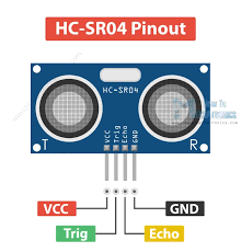
Here is the pinout of the ultrasonic sensor:
- VCC (Power): Connect to the power supply (e.g., 5V)
- Trig (Trigger): Input pin for sending the signal to start the ultrasonic ranging
- Echo: Output pin for receiving the ultrasonic signal
- GND (Ground): Connect to the ground of the power supply
I then connected the pins from the Quentorres board to the ultrasonic sensor according to the pinout.
Then requested assistance from ChatGPT for the code implementation.
const int trigPin = 3;  // Trigger pin of HC-SR04 connected to RP2040 GPIO 3
const int echoPin = 4;  // Echo pin of HC-SR04 connected to RP2040 GPIO 4

void setup() {
  Serial.begin(9600);  // Initialize serial communication
  pinMode(trigPin, OUTPUT); // Set trigPin as an OUTPUT
  pinMode(echoPin, INPUT);  // Set echoPin as an INPUT
}

void loop() {
  // Triggering the ultrasonic sensor
  digitalWrite(trigPin, LOW);
  delayMicroseconds(2);
  digitalWrite(trigPin, HIGH);
  delayMicroseconds(10);
  digitalWrite(trigPin, LOW);

  // Measuring the pulse duration from echoPin
  long duration = pulseIn(echoPin, HIGH);

  // Calculating distance in cm
  float distance_cm = duration * 0.034 / 2;

  // Displaying the distance in Serial Monitor
  Serial.print("Distance: ");
  Serial.print(distance_cm);
  Serial.println(" cm");

  delay(1000);  // Delay for 1 second before next measurement
}
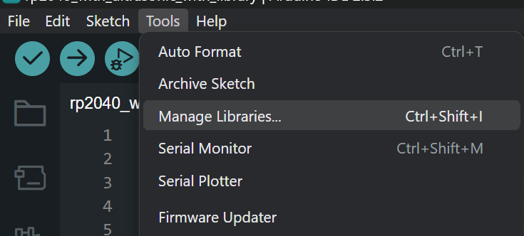
Next, I attempted to rewrite the code, including the necessary library for the ultrasonic sensor.
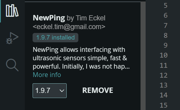
To add the library for the ultrasonic sensor, you need to navigate to the "Tool" menu and select "Manage Libraries." Then, search for "NewPing" and install the library.
Then requested assistance from ChatGPT for the code implementation.
#include <NewPing.h>

#define TRIGGER_PIN  3  // RP2040 GPIO 3
#define ECHO_PIN     4  // RP2040 GPIO 4
#define MAX_DISTANCE 200  // Maximum distance we want to ping for (in centimeters). Maximum sensor distance is rated at 400-500cm.

NewPing sonar(TRIGGER_PIN, ECHO_PIN, MAX_DISTANCE); // NewPing setup of pins and maximum distance.

void setup() {
  Serial.begin(9600); // Open serial monitor at 9600 baud to see distance readings
}

void loop() {
  delay(500);                     // Wait 50ms between pings (about 20 pings/sec). 29ms should be the shortest delay between pings.
  unsigned int distance = sonar.ping_cm(); // Send ping, get distance in centimeters

  if (distance == 0) {
    Serial.println("Out of range"); // Sensor is out of range
  } else {
    Serial.print("Distance: ");
    Serial.print(distance);
    Serial.println(" cm");
  }
}
Everything worked fine as expected.
Wireless Communication
HC-05 (ZG-B23090W): Basic Specs
- Utilizes the csr BC417 chip
- Firmware version: 2.0-20100601 developed by Wavesen
- Configurable as a slave or master device
- Operates in two modes: AT mode and communication mode
- Default baud rate for communication mode: 9600
To utilize the RP2040 and HC-05 (ZG-B23090W) together, I integrated them into a system where the RP2040 would receive data from a mobile app via Bluetooth using the HC-05 module. The mobile app was programmed to send specific data that would trigger the RP2040 to control the onboard LEDs accordingly. This setup allowed for wireless communication between the mobile device and the RP2040, enabling remote control of the LEDs based on the data transmitted over Bluetooth.
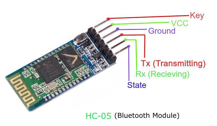
The connection between the HC-05 Bluetooth module and the RP2040 is established as follows:
- VCC (Power) of the Bluetooth module is connected to the 5V pin of the RP2040.
- GND (Ground) of the Bluetooth module is connected to the GND pin of the RP2040.
- TX (Transmit) pin of the Bluetooth module is connected to the 4th pin (receive pin) of the RP2040.
- RX (Receive) pin of the Bluetooth module is connected to the 3rd pin (transmit pin) of the RP2040.
This configuration ensures proper communication between the HC-05 module and the RP2040 microcontroller.
here is the code used
#include <SoftwareSerial.h>
const int ledPin = 0; // GPIO pin for the LED
SoftwareSerial bluetoothSerial(3, 4); // RX, TX pins for HC-05
void setup() {
Serial.begin(9600); // Initialize the serial communication for debugging
bluetoothSerial.begin(9600); // Initialize Bluetooth serial communication
pinMode(ledPin, OUTPUT); // Set the LED pin as an output
}
void loop() {
if (bluetoothSerial.available() > 0) {
char command = bluetoothSerial.read();
// Toggle LED based on received command
if (command == '1') {
digitalWrite(ledPin, HIGH); // Turn on LED
Serial.println("LED ON");
} else if (command == '0') {
digitalWrite(ledPin, LOW); // Turn off LED
Serial.println("LED OFF");
}
}
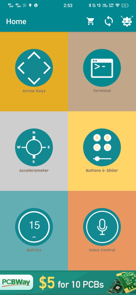
}After uploading the code to your RP2040 microcontroller, you'll need to download the mobile app called "Arduino Blue Control" from the Play Store. This app will enable you to establish a Bluetooth connection with your HC-05 module and send data wirelessly to control the onboard functionality according to the data sent.
This is the interface of the app. On the top right side, there is an option for connecting to the Bluetooth module. Once connected, you can use the terminal feature to input values that need to be transmitted to the RP2040 microcontroller. These values will control the onboard functionality according to the programmed logic in your microcontroller code.
Here is the result after completing the necessary steps:
Wired Communication
SAMDino
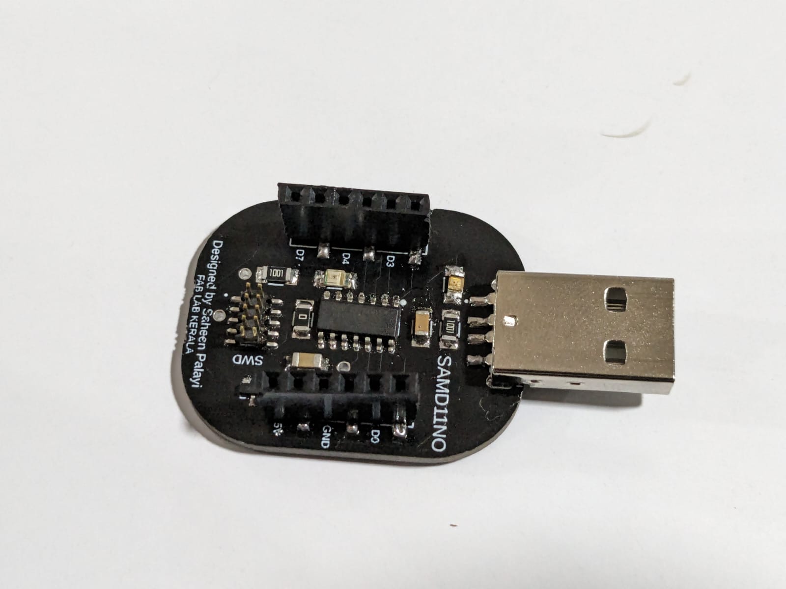
Nextly, Saheen provided the PCB for the SAMDino, so I gathered the components required for the board and soldered them onto the PCB.
This is how it came out
Following this, I commenced programming the SAMDino.
However, before programming the SAMDino, it was necessary to burn the bootloader. To accomplish this, I utilized the Quentorres board and followed the documentation for burning the bootloader.
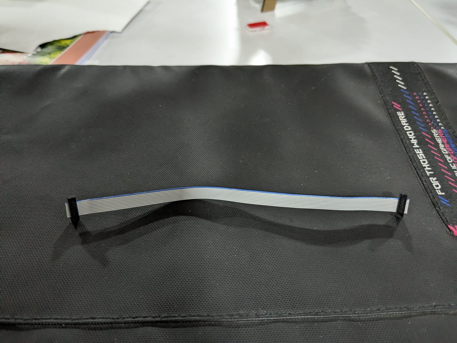
For this task, we require the CBL RIBN 10COND 0.025 cable. Here is the cable with both ends connected to the CONN SOCKET 10POS IDC GOLD.
Then, I connected the SWD pin of both the Quentorres and the SAMDino for burning the bootloader.
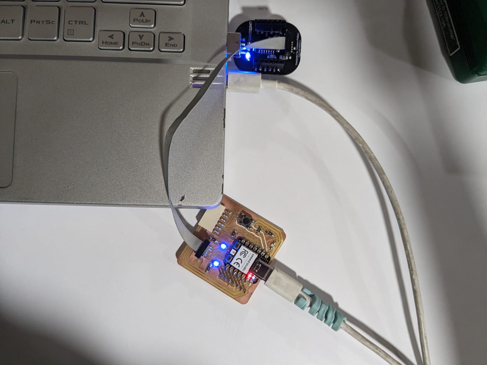
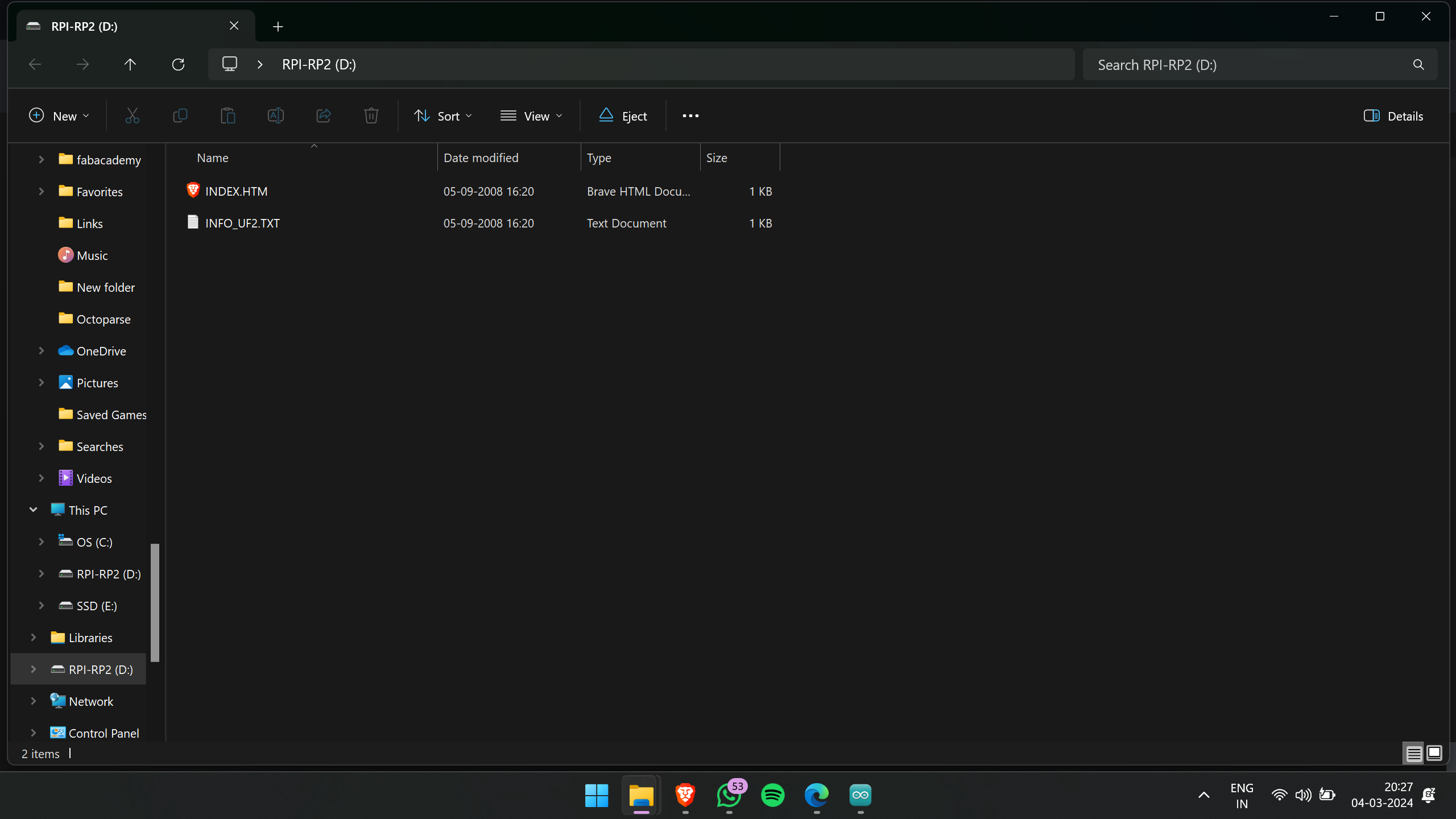
To burn the bootloader onto your board, begin by connecting it to your computer via a USB cable. Press and hold the "B" button, then simultaneously press and hold the "R" button. Once both buttons are pressed, release them. This action triggers the board to enter reset mode, exposing its flash memory as a hard drive.
Next, download the UF2 firmware file and transfer it to the empty hard drive that appears after completing the previous step. Once the file transfer is complete, the board will automatically reset.
Now, the Quentorres board is ready for use.
Next, I proceeded to set up the Arduino IDE platform for burning the bootloader.
Firstly, navigate to the preferences menu in the file menu of the Arduino IDE. Then, add the following link to the additional board manager URLs: https://raw.githubusercontent.com/qbolsee/ArduinoCore-fab-sam/master/json/package_Fab_SAM_index.json
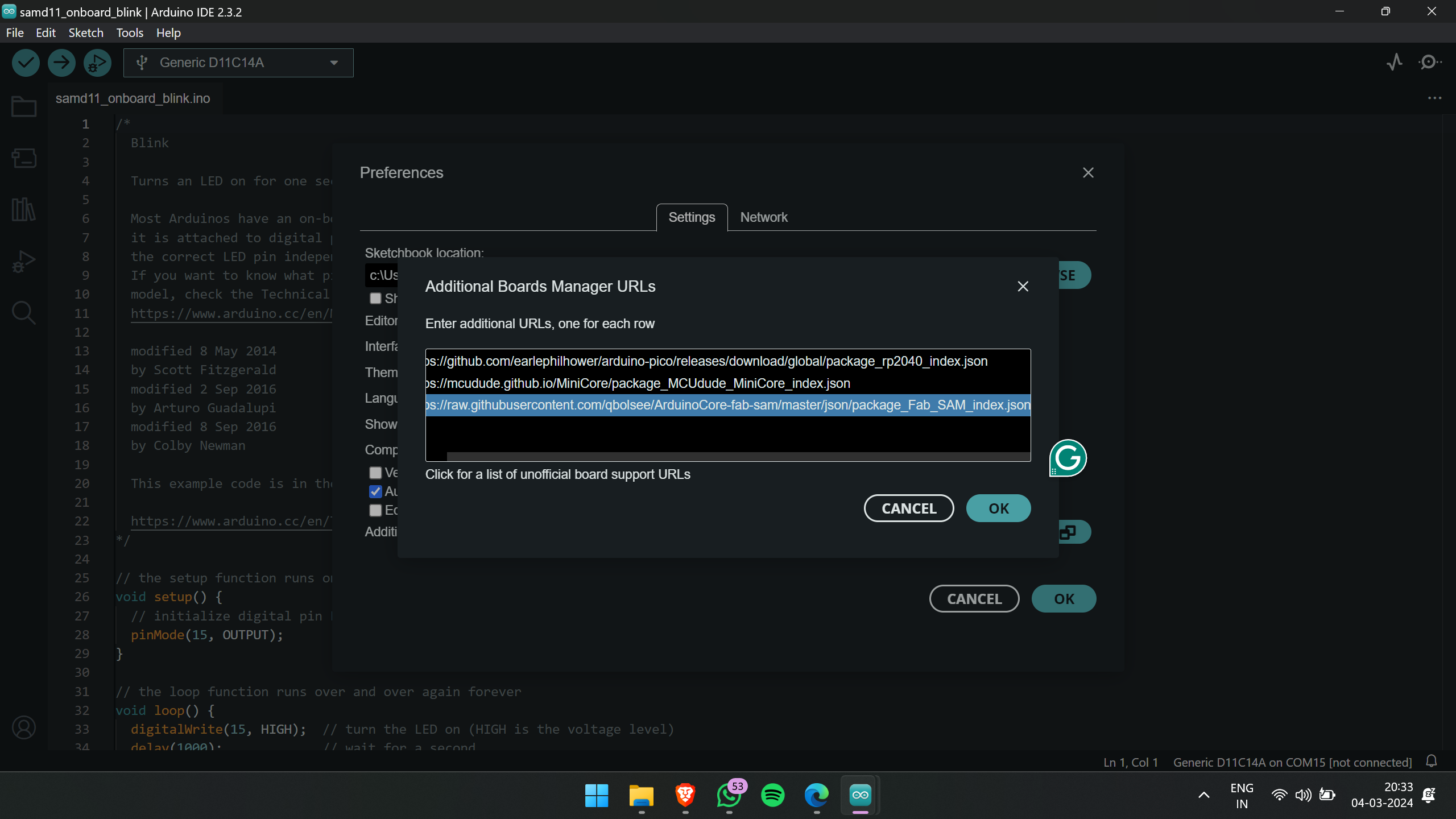
This will allow you to download the Fabcore SAM from the board manager.
After adding the link to the preferences menu and downloading the Fabcore SAM from the board manager, proceed to select the appropriate board and port in the Arduino IDE. Once done, you can then burn the bootloader onto the SAMDino board.
After successfully burning the bootloader.
The next step is to program the SAMDino. Here is a short clip of the programming process.
Initially, I programmed the SAMDino with the basic blink program from the examples menu to make the onboard LED blink.
here is the code used
void setup() {
  // initialize digital pin LED_BUILTIN as an output.
  pinMode(15, OUTPUT);
}

// the loop function runs over and over again forever
void loop() {
  digitalWrite(15, HIGH);  // turn the LED on (HIGH is the voltage level)
  delay(1000);             // wait for a second
  digitalWrite(15, LOW);   // turn the LED off by making the voltage LOW
  delay(1000);             // wait for a second
}
This is how it came
After successfully blinking the SAMDino, I proceeded to add a motion sensor to the SAMDino, specifically the RCWL-0516 Microwave Radar Motion Sensor. I asked ChatGPT for the code and edited the pin numbers to appropriate values
The RCWL-0516 sensor typically has three pins: VCC (Power), GND (Ground), and OUT (Output).
To connect the sensor to the SAMD11 board:
- Connect the VCC pin of the sensor to the 3.3V power supply pin on the SAMD11 board.
- Connect the GND pin of the sensor to one of the GND pins on the SAMD11 board.
- Connect the OUT pin of the sensor to a digital input pin on the SAMD11 board. Make a note of the pin number you choose.
here is the code
// Define the pin for the motion sensor
#define MOTION_SENSOR_PIN 2

// Variable to store the motion sensor state
volatile bool motionDetected = false;

// Interrupt Service Routine (ISR) for motion detection
void motionDetectedISR() {
  motionDetected = true;
}

void setup() {
  // Initialize serial communication
  Serial.begin(115200);

  // Configure the motion sensor pin as input with internal pull-up resistor
  pinMode(MOTION_SENSOR_PIN, INPUT_PULLUP);

  // Attach the Interrupt Service Routine to the motion sensor pin
  attachInterrupt(digitalPinToInterrupt(MOTION_SENSOR_PIN), motionDetectedISR, FALLING);
}

void loop() {
  // Check if motion was detected
  if (motionDetected) {
    Serial.println("Motion detected!");
    motionDetected = false; // Reset the motion detection flag
  }
}
here is the video ouput
MicroPython
MicroPython is a tailored Python implementation designed specifically for embedded systems. It features partial native code compilation, leading to enhanced performance and decreased resource consumption. Unlike CPython, MicroPython is finely tuned for microcontrollers and devices with limited resources. Although it supports only a subset of Python 3.5 features, it excels in tasks involving low-level hardware manipulation and sensor interfacing, making it an excellent choice for IoT (Internet of Things) applications. While MicroPython offers unique advantages for embedded development, it's important to recognize its limitations compared to CPython. Detailed comparisons between MicroPython and other Python implementations can help determine their suitability for different use cases.
For coding in MicroPython, I utilized the Thonny editor. You can download the Thonny editor using this link:
click here
This is the interface of the Thonny editor.
As I'm not proficient in Python, I simply followed this
documentation
blindly.
this the code used form the documentation
from ws2812 import WS2812
import utime
import machine
power = machine.Pin(11,machine.Pin.OUT)//initilizing pin as output
power.value(1)
BLACK = (0, 0, 0) // rgb values for black
RED = (255, 0, 0) // rgb values for red
YELLOW = (255, 150, 0) // rgb values for yellow
GREEN = (0, 255, 0) // rgb values for green
CYAN = (0, 255, 255) // rgb values for cyan
BLUE = (0, 0, 255) // rgb values for blue
PURPLE = (180, 0, 255) // rgb values for purple
WHITE = (255, 255, 255) // rgb values for white
COLORS = (BLACK, RED, YELLOW, GREEN, CYAN, BLUE, PURPLE, WHITE)

led = WS2812(12,1)#WS2812(pin_num,led_count)//Initializes the WS2812 object. It takes two arguments: the pin number connected to the data input of the LED strip (pin 12 in this case) and the number of LEDs in the strip (1 in this case).

while True: // entering the loop
    print("Beautiful color")
    for color in COLORS:
        led.pixels_fill(color)
        led.pixels_show()
        utime.sleep(0.2)
here is the output
Group assignment: click here.
- Browse through the datasheet for your microcontroller.
- Compare the performance of your microcontroller with other architectures.